Friday, February 20, 2009

What is the best configuration of laptop and of which company to purchase under50000?

Latest Configuration of Laptop

Hardware:

Intel® Core™ 2 Duo Processor T8300 (2.4GHz, 3MB L2 Cache, 800MHz FSB)

RAM 4GB Dual Channel 667MHz DDR2

Intel® 965PM / GM Express Chipset

Intel® Integrated Graphics Media Accelerator X3100

Glossy widescreen 14.1 inch display (1280x800)

Intel High Definition Audio 2.0

320GB configured with a 5400 RPM SATA hard drive

8X Slot Load CD/DVD Writer (DVD+/-RW)

6-cell 56WHr Li-Ion Battery

Wi-Fi Wireless 1395 802.11g Mini-Card

Wireless 355 Bluetooth Internal (2.0) Mini-Cards

Software:

Windows Vista OS

Office 2007

Dell Laptop


DellTM StudioTM  14

Processor

Intel®  CoreTM 2 Duo Processor T6400

Operating System

Genuine Windows Vista®  Home Premium

Chipset

Intel®  965GM Chipset

Memory

3GB DDR2 SDRAM

Hard Drive

320GB 5400RPM SATA Hard Drive

Display/Monitor

14.1" Widescreen WXGA CCFL (1280x800) TFT Display with True LifeTM

Network Card

Internal 10/100/1000 Gigabit Ethernet

Graphic Card

Intel®  Integrated Graphics Media Accelerator X3100

Sound Card

Intel®  High Definition Audio 2.0

CD-ROM/DVD-ROM/Disk drive

Slot Load 8X max DVD+/-RW Drive6 with DVD+R double layer write capability

I/O Ports

VGA, RJ11 (via optional USB dongle), RJ45, 3 Audio jacks (1 line-in, 1-line out, 1 Mic-in), 1 Express Card 54mm slot, 2 mini-card slots, 1394a, consumer IR, 3USB 2.0 ports (SR), 1 HDMI, Sim socket

Modem

N/A

Battery

6-cell Primary Battery

Carrying Case

N/A

Service/Warranty

1 Year Limited Warranty (Next Business Day On-Site Service)

Software

Microsoft®  Works 9.0 
Dell Recommends Microsoft
®  Office 2007 Home & Student Edition - OEM Version

Speakers

Integrated speakers

Keyboard

DellTM  Keyboard with Touchpad

Anti-virus

McAfee®  Security CenterTM  30 days Introductory Offer
Dell Recommends McAfee
®  Security Center
TM  15-months OEM

Bluetooth

DellTM  Wireless 370 Bluetooth Internal (2.0) mini-card

Controller Card

DellTM  Wireless 1397 802.11b/g Half Mini Card

Additional Accessories

N/A

Media Direct

Dell Media DirectTM  featuring Instant Office

Webcam

Integrated 2.0 mega pixel web cam

Card reader

8-in-1 Memory card reader

Color Kit

All colors available

Remote & Ear Buds

DellTM  Travel Remote Control & Noise Isolation Ear Buds

Strike Zone

Strike ZoneTM  Shock Absorber

Security Feature

Sensible Vision Fas tAccess Facial Recognition Software

Tuesday, February 17, 2009

TROUBLESHOOT THE SYSTEM BOARD


In this basic motherboard troubleshooting tutorial, you will learn about system board configurations, ROM BIOS troubleshooting, basic hardware components, physical memory and basic configuration errors and system memory basics. This motherboard configuration and microprocessor troubleshooting tutorial help you identify the basic system board problems. There are many replacable components on a mother or system board such as RAM, ROM, CMOS battery and ROM BIOS. If any of these components functions improperly, you can replace the faulty components with the new components. The Microprocessor and the ROM BIOS are the two major components that are responsible for the problems that are generated for the system board. While proceeding with the troubleshooting, you should from the Microprocessor and the ROM BIOS. There are a large number of the hardware failure symptoms that are associated with the system board. Typical symptoms associated with system board failure are the following.
1. The system locks up during working
2. The system produces a one long beep and 3 short beeps.
3. Current time and time disappear or changed.
4. DMA error message occurs
5. Low CMOS battery message appears.
6. CMOS checksum failure message appears
7. A 201 error message appears which indicates the RAM failure.
8. A Parity check message appears which also indicates the RAM error.
9. The On/Off indicator lights of the system are working, hard drive is also spinning up but there is no boot up starts.
10. The On/Off lights are working and there is also a display on the monitor but the hard disk doesn’t starts up and no system boot ups occur.
Configuration Problems
The configuration problems are most likely to occur when the system starts up for the first time or there is some new installation has been performed on the system. The values and configurations that are stored in the CMOS but accurately reflect the configurations. Incorrectly CMOS values results in the associated hardware to fail. In the advanced CMOS settings, check the enabling functions as a part of the hardware configurations. There are many configuration options in the modern BIOS and a user must have the knowledge of how to configure them. If you can see the startup screen on which BIOS information is displayed, you can consider that there is not basic hardware configuration problems exists in the basic hardware components. After this point, the system starts to load the device drivers and other additional components information and next to this point, the system loads the operating system. If the error occurs after the CMOS display and before the boot up tone, you must clean boot the system.
Microprocessors Troubleshooting
If the Microprocessor fails to work, you must hear a slow beep sound or no display occurs at the monitor screen. This tells that some internal hardware or configuration errors have stopped the microprocessor’s internal circuitry to work. Some kinds of internal problems allow microprocessor to work but in case of extra working, microprocessor fails to perform additional work. The best solution for the microprocessor’s problems is to replace it with a new one. If the system locks up for a continuous few minutes, this means that the fan of the microprocessor or the internal cooling mechanism is not working properly. In this scenario, you should replace the fan of the microprocessor to provide it continuous cooling.
RAM Errors
RAM is a serviceable part of the system board and the RAM failure basically can be categorized into the following two categories. Soft-memory errors: Soft memory errors are the errors that are caused by the infrequent glitches in the operation of the system. These errors can be controlled just by restarting the system. Hard-memory errors: Hard memory errors are the permanent physical errors and that requires that memory units should be checked properly and replaced.
ROM BIOS Setup Erros
A malfunctioning or damaged ROM stops the systems’ working completely. If the system board is dead, you should first examine the BIOS chip for any kind of physical damage. If the BIOS chip is heated up, it is most likely for it to crack. Another symptom that points towards the damaged RAM is bootup sequence automatically moves into the CMOS configuration display. In this situation, you must replace the faulty BIOS chip with another one, which matches according to your system’s configurations. Another cause of the system’s failure or problem is the malfunctioning of the CMOS battery. If the system fails to display the current time and date, the most likely reason for this is the faulty CMOS battery and the only solution for this is to replace the battery with the new one. In case the battery is replaced, the configurations and settings in the CMOS chip are lost, the only method for the configuration is to access the CMOS batter and reconfigure the system.

How to install Windows 2000 Server


In this section you will learn the basicss of windows 2000 server installation, how to install window, active directory, domain controllers, system configurations. Being a network administrator or Microsoft Windows 2000 Server support professional, one of your job description tasks is Windows Server Installation.
Step #1: Planning for your installation
When you run the Windows 2000 Server setup program you must know that how to install the Windows 2000 server. Thorough planning can make you avoid potential problems during the installation process. So, it’s necessary to do some paper work and make a good plan before installing the Windows 2000 server operating system. You must know the needs of your office network, server hardware and software to be installed on your server.

Without a proper plan Potential problems can occur in the future and work can become more hectic. There are some important points, which you should take into account before starting the installation process.
1. Check System requirement2. Check hardware and software compatibility3. Check the disk partitioning options4. Select the file systems according to your needs.5. Decide workgroup or domain installation6. Complete a pre installation checklist.Once you are making sure about these things you can start the installation process.
Step #2: Starting the installation process
You can install Windows 2000 Server in different ways, all the methods are valid and which method you choose is depends on your needs and limitations. Manual installation process can be divided into different ways as followings.
• Boot from CD- This is a fresh installation and no existing partition is required.• Boot from the 4 setup disks and then insert the CD, in this way also not existing partition is required. • Boot from an MS-DOS startup floppy disk, go to the command prompt, create a 4GB FAT32 partition with FDISK command, reboot the computer, format the C partition, you have created and then go to the CD drive, go to the i386 folder and run the Winnt.exe command. • In the other methods, run an already installed operating system such as Windows NT 4.0 Server and from within the NT 4.0 go to the i386 folder in the Windows 2000 Server installation CD and run the WINNT32.exe command. This will upgrade the Windows NT Server 4.0 to the Windows 2000 Server.
• Alternatively, if you want to upgrade from Windows 98 into Windows 2000 Professional you can follow the same steps as I have described in the above installation method. But you cannot upgrade Windows 98 into Windows 2000 server.
Additionally, there are other automated installation methods, such as uninstallation method by using an unattended file, using Sysprep, using RIS or running the uninstallation method by the CD itself.
It doesn’t matter that which installation method you use to install Windows 2000 Server or Professional. All methods look alike and the main function is the same.
Step #3: Text based portion of the setup
The setup process starts loading a blue-looking text screen. In this way you will be asked to accept the license agreement EULA and choose a partition on which you want to install Windows 2000 and you will be also asked to format the partition if the partition is new FAT, FAT32 or NTFS. The setup process begins loading a blue-looking text screen (not GUI).1. Select to boot the computer from CD.
2. At this stage you can press F6 if you need to install the additional SCSI adapters or other storage devices. If you choose it then you will be asked to provide the floppy disk for the drivers.
3. Setup will get all the required drivers and files. 4. Now select to setup Windows 2000. At this point, if you want to fix some problems in the previously installed operating systems then you will have to press R. If not, then just press enter to continue with the fresh installation. 5. If you haven’t made any partition then you will get a warning message to create a partition and delete the old partitions. You can specify the partition size here. If you want to continue then press C.
6. Accept the license agreement and press F8.• Select or create the partition on which you will install W2K. • If you hard disk is already partitioned but don’t have enough disk space for the installation, you can create an additional partition from the unpartitioned space. If the hard disk is already partitioned, but has enough unpartitioned disk space, you can create an additional partition in the unpartitioned space. If the hard disk already has a existing partition, you can delete it to create more unpartitioned space for the new partition. By deleting the old partition you will delete all data on that partition.
If you select a new partition during Setup, create and size only the partition on which you will install Windows 2000. After installation, use Disk Management to partition the remaining space on the hard disk.
7. Select the file system like FAT32, NTFS for the installation partition. After you create the partition, select a file system. After selecting the file system, it will ask you to format the disk. Windows 2000 supports FAT, FAT32 and NTFS file system. You can get access to the local data on your hard disk, if it is formatted with the NTFS and if your operating system is Windows Server 2003, Windows XP Professional, Windows 2000 and Windows NT. If you plan to get data on your local hard disk’s drive where Windows 95 or Windows 98 is installed then you will have to use FAT or FAT32 file systems.
8. Setup will then begin copying files after formatting the disk, from the installation point (CD, local i386 or a network share).
9. After copying files step is completed the computer will be restarted in the graphical mode. Step #4: Graphical user interface (GUI) based setup portionAfter the first reboot and copying the necessary installation files the setup comes in the graphical mode.
Next it will load the device drivers based on the hardware it finds in your computer. At this point, you can change the regional settings if you want.1. Install the Hebrew language support at this point.2. Here type your name and organization name.3. Next type product key.4. Enter the appropriate license types and the number of the purchased licenses. 5. Here you type the computer name and the password of the local administrator account. The local administrator account is based in the SAM of the computer and is used for the locally administrative tasks4. Next choose which network or other components to be installed on the system. 5. Next select the date, time and zone settings. 6. Setup now will install the networking components. Press Next to accept the typical settings option if you have one of the following situations:• You have DHCP on your network.• Your computer running Internet Connection Sharing (ICS).• You are in a workgroup environment and do not plan to have any other servers or Active Directory at all, and all other workgroup members are configured in the same manner.Otherwise select Custom Settings and press Next to customize your network settings.7. You should highlight the TCP/IP section and press Properties.In the following general tab enter the necessary information. You should specify the IP address, and if you don't know what the Subnet Mask entry should be - you can simply place your mouse pointer over the empty area in the Subnet Mask box and click it. The operating system will automatically detect the settings.
If you are a stand alone computer or you don’t have the sufficient rights, leave the default entry selected and press next.8. In the next stage setup process will finish copying files and configuring the setup. 9. Next the setup process finishes and displays the finish window.10. Next Windows 2000 reboots and you after reboot you get the CTRL-ALT-DEL window.11. Congratulations. You are done. Windows 2000 has been installed on you computer.

How to Install ISA 2000 Server

Introduction to ISA Server
ISA or Internet security
and accelerator server is a proxy server by Microsoft and it is a part of .Net products. ISA server provides the basic services of Enterprise, Firewall and Cache server. ISA server is designed to work with Windows 2000 and the later editions of Windows. ISA server comes in two editions standard edition and Enterprise edition. Standard edition is a standalone edition that supports four processors.
Enterprise editions are for large scale networks and they support more than four processors. Firewall, policy based administration, virtual private network support, Dynamic IP filtering, Intrusion detection system, web cache, gatekeeper and the client deployment are the basic components of the ISA server
Software and Hardware Requirements

256 RAM
2 GB Free space on NTFS drive
Minimum 300 MHZ or higher processor
200 MB of available space of installation
ISA Server Service Pack 1
Installing ISA Server on Windows 2000 Server
1. Make sure that Windows 2000 Server is installed on the machine where you want to install ISA Server.
2. Put your ISA server 2000 CD in the CD-ROM
3. Click on the Install ISA server link.
4. An ISA 2000 server dialog box will appear that will inform you to install service pack 1
5. Click continue on the welcome page.
6. On the next screen enter the CD-Key where the CD-Key box appears.
7. Next click I agree on the Server’s license agreement page.
8. Click the full installation button.
9. On the next page, select the integrated mode option. Integrated mode has both the features of web proxy and firewall mode.
10. On the next (web cache page), select the NTFS drive and click the set button.
11. Press Ok.
12. On the local address table page, click the construct table button and remove this check box “Add the following private ranges”.
13. Put a check mark “Add address ranges based on the Windows 2000 Routing Table checkbox”.
14. Click ok on the local address table box.
15. Next click ok on the dialog boxes.
How to Install Server Pack 1
You can download the ISA server service pack 1 from the following path
http://www.microsoft.com/isaserver/downloads/sp1.asp
1. Double click on the file isasp1.exe after copying the setup files on the ISA server machine.
2. Type in the path for the temporary files.
3. Click I agree on the EULA dialog box.
4. Click Ok to “Microsoft ISA Server 2000 Update Setup” and the computer will be restarted automatically.

Jumpers

Jumpers are small devices that are used to control the operation of hardware devices directly, without the use of software. They have been around since the very first PCs, and are still used on many types of modern hardware today. A jumper consists of two primary components:
Jumper: The jumper itself is a small piece of plastic and metal that is placed across two jumper pins to make a connection, or removed to break a connection. They come in a few standard sizes (and some non-standard ones I'm sure); only one or two sizes are commonly seen on PCs. Jumpers are sometimes also called shunts.
Jumper Pins: A set of pins, across two of which a jumper is placed to make a specific connection.
Note: Some people actually call the jumper pins the "jumper"; others call the pins plus the jumper a "jumper". The terms are used rather loosely, but it's nothing to worry about.
A jumper is a mechanical switch that is easily modified by hand. Essentially, it's a circuit that has been broken intentionally and a pin placed on each end of the broken connection. Placing a jumper across two pins connects them electrically, completing the circuit; removing a jumper from a set of pins breaks the circuit. Hardware engineers allow users to configure devices or change their operation by creating different sets of pins that implement different functions depending on how the jumpers are set. When power is applied to the device it detects which circuits have been closed or opened. The most common place where most folks see jumpers are in hard disk drives and motherboards. On hard disks they are typically used to tell the hard disk what role to play on the hard disk interface cable; on motherboards they control as many as a dozen different settings related to how the motherboard functions. Usually these jumper settings are printed directly on the hardware for convenience.
The main advantage of using jumpers for controlling hardware is that they are simple and straightforward: if you get the settings correct, the hardware (assuming it is not defective) will perform as it should. What you see is what you get. The biggest disadvantage associated with using jumpers is the fact that they require physical manipulation. If you need to change a jumper, you have to physically open the PC to access the device, and that's not always easy to do. The jumpers are also very small and easily lost if you are not careful. Also, you have to make these changes with the power off. These issues are one reason why the effort was made a few years ago to move away from jumpers on hardware devices and towards software configuration of hardware using techniques such as Plug and Play.
Jumpers are given many different designations. On motherboards, it is common to see them numbered, using a sequence such as "JP1", "JP2", etc. For some functions, jumpers are treated as a group--multiple jumpers must be placed on particular sets of pins to enable or disable a specific function. The documentation that comes with any hardware device should tell you how to set its jumpers to control various functions; if you don't have the documentation, check the manufacturer's web site.

A group of jumper pins on a motherboard, showing three jumpers connected and two sets of pins "bare" (no jumpers attached).Note the "JP7" and "JP15" labels in the foreground

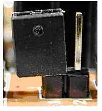
One problem experienced by many who work with hardware occurs when a jumper needs to be removed from a set of two pins to disable a function: what do you do with it? Some keep a big "box o' miscellaneous hardware" for jumpers and similar small items, but since the jumpers are small and easy to lose, one trick that is often used is to "dangle" the shunt by connecting it to only one pin. Since the second half of the shunt is disconnected, this is electrically equivalent to removing it altogether, and ensures that it will always be there for you the next time you need it.

A jumper "dangled" from a set of pins. This is electricallyequivalent to removing the jumper entirely.

Client installation


Installing Windows 2000 Professional
In this section you will learn how to install Windows 2000 Professional. The basic steps, which are required for the installation and configurations. There are different methods of installing the Windows 2000 Professional.There are two basic types of the installation.
Fresh Installation2. Dual Boot Installation
In the fresh installation method, Windows 2000 is installed as the only operating system on a formatted or empty hard disk. In the dual boot installation method Windows 2000 Professional is installed alongside another operating system on the same hard disk such as Windows NT, Windows XP, Windows 98 or Red hat Linux. All the operating systems are needed to be installed on the separate portions of the hard disk.
Just start from the Windows 2000 Professional installation CD. Make sure that your computer is set to boot from the CD first. To get the grip on Windows 2000 Professional installation and for easy to understand, I have discussed all the installation methods in the following points.
1. Insert the Windows 2000 Professional in the CD-ROM and start the computer and when you are prompted press any key to start the Windows 2000 Professional setup program.2. Start from the boot disks, insert the disk first and then remaining three floppies when you prompted.
3. Insert the CD-ROM and then at the command prompt type drive:\1386\winnt32.exe and then press Enter or if there is no previous installation on this computer then type drive:\i386\winnt.exe and press Enter, where drives a letter of your CD-ROM drive. Setup starts and begins to inspect your computer’s hardware configurations and load device drivers and other necessary installation files.
4. Press Enter when Microsoft Windows 2000 Professional screen appear.
5. Press F8 to accept the license agreement and continue the installation.
6. Next either creates a new partition by pressing C and deletes the old partitions.
7. Format the partition by using the FAT 32 or NTFS file system and press Enter.
8. Setup formats the partition by the file system you selected and then begins to copy the installation files on your selected drive. After all the installation files copies in the first step, system restarts.
9. After the first restart, GUI interface starts click next to continue the setup. Setup detects and installs the device drivers of specialized mouse and keyboard.
10. When the regional settings appear customize your installation for locale, format, number, currency, time, date and language if necessary. After this does not press start from CD-ROM when your computer restarts.
11. In the personalize dialog box, type your name and your company name. In the product ID dialog box type 25 character key. Press next in the computer name and password dialog box, either accept the default computer name or assign a customize computer name. You can set the password for the local administrator account.
12. In the date and time settings, select the correct data and time. Here you can also specify which time zone you are in, and set the computer to automatically adjust the clock for daylight saving time.
13. Click next setup will detect the networking software and settings, either select the typical to set default network settings for File and print sharing for Microsoft networks or choose the customized settings for your network such as IP address, workgroup or domain name, DHCP server settings etc.
14. During the final stage of installation, setup installs start menu items, registers components, saves settings and removes the temporary files, which were created during the installation. When Completing Windows 2000 Setup Wizard dialog box appears, remove the CD from the CD-ROM and click finish to restart the computer.
15. After the computer restarts, click next in the Welcome to the Network Identification Wizard dialog box. In the users of this computer dialog box, either specifies that user musts enter user name and passwords or select Window 2000 Profession should automatically log on a specific user. Click finish.
In this tutorial, I have covered the basic steps, necessary to install Windows 2000 Professional. You can find the separate tutorials on how to create the Boot Disks, which are necessary for the installing the Windows 2000. You have the option to skip the boot disk creating portion. You can even install the windows without inserting the floppy disks for creating the boot disks.

Monday, February 16, 2009

What Happens When You Press A Key


To illustrate how the computer works, let's take a very simple example. Let's suppose you are working in your word processor and you type the letter "M". Here's what happens, in general terms, when you press the "M" button:
The keyboard sends an electrical signal, called a scan code, to the computer saying that a button was pressed.
The keyboard controller interprets the scan code and determines that the letter pressed was an "M". It stores this "M" in a special memory location until the processor is ready to deal with it.
The controller sends a signal to the processor, called an interrupt. An interrupt tells the processor that some part of the computer has information for it to process and wants its attention. In this case, the keyboard controller wants the processor to look at the key you just pressed.
The processor is almost always doing many things, sharing its time among many tasks. As a result, most every event must wait its turn. The processor services interrupts based on their priority. When it is time to deal with the keypress, the processor routes it to the program for the operating system that you are using.
Assuming you are using a multi-tasking operating system like Windows, the operating system software decides which window you pressed the key in and sends a message to that window telling it a key was pressed.
The window decides what to do with the keypress. Since in this case it's your word processor window, and the key you pressed was an ordinary letter, the word processor will add that letter to its working area for the file you have open. The letter will take one byte of your computer's memory (RAM). Other keys could be handled differently (for example, if you pressed the key to tell the word processor to exit).
The window will then call the operating system to display the letter on the screen.
The operating system will display the letter on the screen by adding it to your video card's video memory.
The next time the video card refreshes your monitor (re-displays what is in its video memory) the letter will appear on the screen. Most video cards refresh the monitor between 60 and 100 times per second.
Wow, a lot happens even in a simple example like this! This all appears to occur instantaneously because the computer is simply operating at a much faster speed than humans can readily perceive. But despite the illusion created by the speed of the PC, a lot of activity is going on inside the box for even the most basic activity.
In fact, even in the description above, I omitted many steps and details. To list every single step could take dozens of pages, even for just this simple example! The processor itself is handling many thousands of chores every second, and every part of the computer has a job to do on an ongoing basis. This hopefully gives you some idea of how the computer processes, moves, and stores information. Notice that in this example all three activities occurred.

Saturday, February 14, 2009

What is Subnetting?


Here you will find subnet network overview, ip addressing, address translation, network overview, subnet masking and subnetting overview. A subnet or a subnetwork is a separate part of an organization’s network. In a subnet all the machines are typically in one room, building or at one geographical location.
By dividing an organization’s network into the subnets allows it to connect to the internet by using the same shared network address. Without subnet’s an organization may get different connections to access the internet. Subnetting is the modification of a single IP network to create two or more logically different networks.
A subnet allows the flow of network traffic between hosts to be segregated based on the configuration of a network. Subnetting can improve the network security and performance by arranging the hosts into the different logical groups. Subnetting is required when one network address needs to be distributed across multiple network segments. Subnetting is required when a company uses two or more types of the network technologies like Ethernet and Token Ring.
Two network segments are restricted by distance limitations. Submetting or dividing the network into the segments is also required when localized network management is required for example accounting, sales, customer service departments. There is another reason for the subnetting, which is that the computers on the network, which use more bandwidth, needs to be separated from the rest of the computers. There are certain advantages and disadvantages of the subnetting. Before you start dividing your network into the different segments, you should assign the IP address to each computer in your network segment.
Subnetting makes the network management easier and it is also very helpful for the troubleshooting of a network segment. The internet is a collection of networks where users communication with each other. Each communication on the internet carries the source and the destination address of the computer. This address is called IP address. This 32 bit address has two parts: one part represents the network portion and the other part represents the host portion of the IP address. A company can use some of the bits in the machine or host portion of the address to identify a subnet. In this scenario, the IP address contains three parts: the network address, the subnet address and the machine address.
Subnet Mask Basics
The most recognizable part aspect of subnetting is the Subnet mask. A subnet mask contains 4 bytes, 32 bits and is divided into 4 period separated octets. Typically, a very common subnet mask in binary looks like this.
11111111 11111111 00000000 00000000255 255 0 0
How to Apply a Subnet Mask
A subnet mask does not work like an IP address and it cannot exist separately without an IP address. An IP address and subnet mask work together to form a network. An IP address splits into two main parts when applying the subnet mask. The leftmost bits of a subnet mask must be set to 1. For example
11111111.00000000.00000000.0000000011111111.11111111.00000000.0000000011111111.11111111.11111111.00000000
The above example shows the valid representation of a subnet mask into the binary numbers.
00000000.00000000.00000000.00000000 is an invalid subnet mask. 11111111.11111111.11111111.11111111 is also invalid subnet mask.
All valid subnet masks contain two parts: the left side with all mask bits set to '1' (the extended network portion) and the right side with all bits set to '0' (the host portion), such as the first example above.
Subnetting an IP network can be performed for a variety of reasons such as using the different physical media in an organization, such as FDDI, WAN and Ethernet, preservation of the addresses and for the purpose of security, management and ease of troubleshooting. The most
common reason of the subnetting is to control the network traffic. In an Ethernet network, all computers in a segment see all the packets that are transmitted by all the other computers on the same segment.
In this situation, the network performance can be badly affected due to the heavy traffic loads, collisions and the retransmission of the packets. A router is used to connect the IP networks and it also helps to minimize the load of the traffic.
Subnet Masking
By applying the subnet mask to the IP address you can identify the network and host portion of the IP address. The decimal number 1 represents the network portion in the subnet mask and the node is represented the 0s. Performing a logical AND operation between the IP address and the subnet mask resulting in the network address. For example, using our test IP address and the default Class B subnet mask, we get: 10001100.10110011.11110000.11001000 140.179.240.200 IP address of the class B11111111.11111111.00000000.00000000 255.255.000.000 Default subnet mask of class B--------------------------------------------------------10001100.10110011.00000000.00000000 140.179.000.000 Network Address value
The following example shows the default subnet masks.• Class A Subnet Mask- 255.0.0.0 - 11111111.00000000.00000000.00000000 • Class B Subnet Mask- 255.255.0.0 - 11111111.11111111.00000000.00000000 • Class C Subnet Mask- 255.255.255.0 - 11111111.11111111.11111111.00000000
Subnetting Review
Subnetting allows network and system administrators some flexibility in defining relationship among the hosts of a network. Hosts on the logically and physically different subnets can talk to each other through specialized devices called gateway or router. The ability to filter the traffic between
subnets can make the more bandwidth availability. Subnetting referred to as subdivision of a class based networks into subnetworks.
A router can exchange subnet routes with the other routers in the network. A subnetted network can’t be split into the isolated portion. All the subnets must be contiguous because the routing information cannot be passed to a non-network member. Router can exchange subnet routes with other routers within the network. Since the subnet masks are identical across the network, the routers will interpret these routes in the same manner. However, routers not attached to the subnetted network can't interpret these subnet routes, since they lack the subnet mask.
Therefore, subnet routes are not relayed to routers on other networks. This leads to our second
restriction. Subnetting allows you to create multiple logically different networks within the same class A, B or C. If you break a major network into smaller networks, it allows you to create a network of interconnecting subnetworks. Any device or gateway that is responsible for connecting the different subnetworks must have the distinct IP address one for each subnetwork.
To subnet a network use and extend the natural subnet mask using some of the bits from the host ID portion to create a subnetwork ID. In this example, given a Class C network of the IP address 4.15.5.0 which has a natural subnet mask of 255.255.255.0, you can create subnets in this manner:
11001100.00001111.00000101.00000000 204.15.5.011111111.11111111.11111111.11100000 255.255.255.224
---------------------------------subnet----
By extending the natural subnet mask to be 255.255.255.224, you have used three bits from the host portion of the mask and used them to make subnets. By using these 3 bits, it is possible to create 8 subnets. The remaining five ID bits of the host portion, each subnet can make 32 host addresses and the 30 addresses out of 32 are assigned to the devices or computers. The host IDs
of all zeros and all ones are not allowed.
204.15.5.0 255.255.255.224 host address range 1 to 30204.15.5.32 255.255.255.224 host address range 33 to 62204.15.5.64 255.255.255.224 host address range 65 to 94204.15.5.96 255.255.255.224 host address range 97 to 126204.15.5.128 255.255.255.224 host address range 129 to 158204.15.5.160 255.255.255.224 host address range 161 to 190204.15.5.192 255.255.255.224 host address range 193 to 222204.15.5.224 255.255.255.224 host address range 225 to 254